Pipework Vibration ‘How-To’ Guides
We would welcome your suggestions for other ‘How-To’ guides. Please send us a message via the BLOG page or CONTACT US page
#1 How to Solve SBC Problems
Did you know that one of the biggest causes of vibration induced fatigue failure is also one of the easiest to fix?
Small Bore Connections (SBC) are welded connections between smaller pipes (typically 0.5″ and 2″) and main line pipes. These welded connections are highly prone to vibration induced fatigue failures and account for the majority of pipework fatigue cracks.
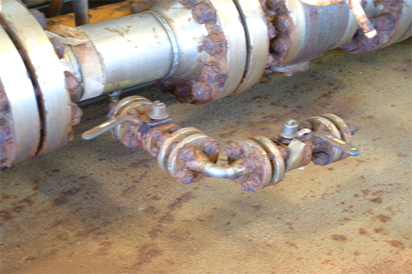
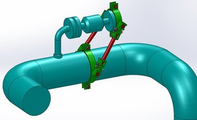
VibTech recommends the following simple 8 stage process for tackling SBC risks:
- Arrange for key personnel to attend a VibTech 2 or 3 day training course
- Hire a Pipework Vibration Assessment Meter from VibTech for a week or two
- Perform your own SBC vibration assessments on all SBCs (Put your training into practice)
- Identify any SBCs with levels above ‘Concern’ (very easy)
- Measure just 3 simple dimensions on the SBC (2 diameters and a length)
- Order a new AVT Easy-Brace™ Universal SBC brace (guaranteed to fit!)
- Fit the brace yourself (simple bolt-on retrofit solution)
- Final check to verify that vibration levels are now below Concern
#2 Quantitative Main Line LOF Assessment
Section T2 of the EI Guidelines contains methods for the calculation of Likelihood of Failure (LOF) for a whole range of excitation mechanisms.
The methods in each Section are in the form of Flowcharts combining decision processes and corresponding LOF calculations
Calculation methods for the following 8 Excitation Mechanisms are included:
- Flow Induced Turbulence
- Mechanical Excitation
- Pulsation: Reciprocating/Positive Displacement pumps and compressors
- Pulsation: Rotating stall
- Pulsation: Flow Induced Excitation
- High Frequency Acoustic Excitation
- Surge/Momemntum changes due to valve operation
- Cavitation and Flashing
The quantitative analysis section T2 is one of the most daunting sections of the EI Guidelines and requires a high level of mathematical skill to be able to accurately follow the flowcharts, completing the multiple stages of calculations at each decision process step.
VibTech Ltd has produced a powerful Excel based Quantitative Main Line LOF Assessment Tool to simplify and automate the LOF calculation process for Main Lines
The Vibtech ‘Quantitative Assessment Tool’ (QAT) is a spreadsheet solution which removes the need for the engineer to perform any calculations in performing quantitative main line likelihood of failure (LOF) assessments..
The VibTech process is simply as follows:
- Ideally arrange for key personnel to attend a VibTech 2 or 3 day training course (even though the calculations are done for you, the person doing them should still be deemed to be competent)
- Purchase a commercial copy of the VibTech ‘Quantitative LOF Assessment’ spreadsheet (Contact us for latest price’ section)
- Select a Code corresponding to the required Quantitative LOF Assessment excitation Mechanism e.g. FIV, FIP, AIV etc
- The spreadsheet will then produce a concise input form, including all parameters required fro calculations plus all data required for any decision making processes.
- Simply fill in the input form from process data and mechanical data
- As soon as the last value is input, the calculated LOF is displayed together with several intermediate results (useful for data validation).
- The spreadsheet enables calculations to be performed for up to 250 conditions at a time and is very useful for performing ‘what-if’ assessments. i.e. copy same data into the next columns but vary some key parameters such as flow velocity, pipe diameter or wall thickness to immediately see the effects on calculated LOF.
- An overall combined results table shows LOF results for each position for each excitation mechanism.
Download a PDF copy of VibTech’s unique Quantitative LOF Assessment Tool (QAT) brochure.
#3 Important New Guidance for Small Bore Tubing (Instrument Tubing)
Did you know that in July 2013, the Energy Institute published radically new guidance on Small Bore Tubing aimed at reducing the likelihood of tubing failures?
One of the biggest changes is the recommended replacement of traditional ‘pigtails’ with a new ‘Rectoil’ rectangular coil.
The publication ‘Guidance for the design, installation and management of small bore tubing assemblies’. 2nd edition, May 2013 (ISBN 978 085293 651 1) contains a number of very important recommendations to prevent tubing failures, which account for a high percentage of all operational failures.
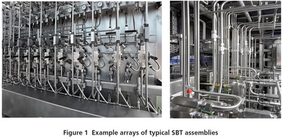
Small Bore Tubing (SBT) refers primarily to stainless steel instrument tubing of diameter typically 6 – 12mm (1/4″ to 1/2″) with screwed fittings containing sealing ferules.
Don’t underestimate the risk
Statistics collated for the period 2009 to 2010 indicate that:
- 20,4 % of all reported hydrocarbon leaks recorded on the Hydrocarbon Release(HCR) database were related to ‘instruments’, i.e. they are regarded as SBT related.
- Of these, 11 % of all reported HCRs events were classed as major or significant severity events.
- 68 % of all ‘instrument’ leaks were gas releases, for which the ‘significant’ severity threshold was breached (notionally an amount greater than 1 kg).
It should be noted that complete fracture of a section of SBT, or parting of an SBT coupling, can potentially rapidly escalate to a major release in just a few minutes.
For example, release from a 6 mm diameter hole in a gas system operating at around 150 bar can result in a major severity release (i.e. > 300 kg) in around eight minutes.
The new guidance addresses 4 main areas:
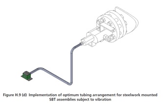
- Structure Mounted Arrangement
- Pipework Mounted Arrangement
- Large Scale Deformations
- Management & Competence
The key points of the recommendations for each of these are detailed below
Structure Mounted Arrangement
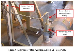
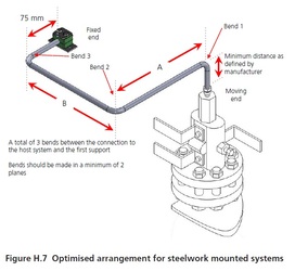
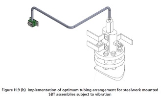
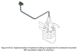
This relates to SBT which spans between a Main Line pipe and a fixed point on a nearby structure.
- SBT pipe run must contain 3 bends
- Guidelines specify the minimum length of each straight section
- Bends 1 & 2 must be in different planes
- Structure support must be > minimum distance from Bend 3
- Pipe pends must be > minimum distance from fittings
- Pipe must support no additional components


Large Scale Deformations
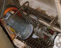
SBT runs must be designed to accommodate Large Scale Deformations (e.g. due to Main Line thermal expansion).
Traditionally, this type of movement was always enabled by incorporating ‘pigtails’ (multiple circular coils of tubing) within the SBT runs
One of the most radical recommendations within the new guidance notes is the replacement of ‘Pigtails’ with ‘Rectoils’.
Laboratory testing by Xodus has shown that Pigtails are not the most effective method of reducing SBT stresses caused by large scale deformations.
In contrast, the rectangular coil design of the ‘Rectoil’, when applied in thecorrect way and with the correct geometry can offer superior performance.
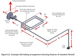
The design of the Rectoils is covered in great detail in the guidance notes and is very prescriptive, including:
- Precise minimum lengths for all Rectoil sections R1, R2 & R3
- Precise minimum lengths for all pipe straight sections A, B & C
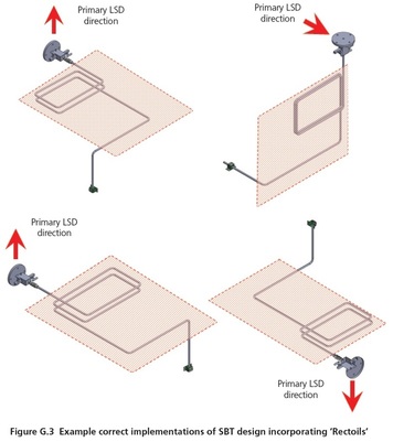
- Precise orientation (short side of Rectoil must be in 1st pipe run (line A)
- Precise spacing between the coils of the Rectoil
- Precise orientation of Rectoil such that the direction of expected largest deformation will cause separation of coils within the Rectoil.
Management and Competence
The new guidelines also place great emphasis of Management and Training.
Operating companies should have policies and strategies in place that ensure the integrity of SBT assemblies on installations is retained over their entire life cycle. This should be achieved through its management systems where policies and strategies for management of integrity of SBT assemblies have been specifically identified and engineering specifications and/or philosophies for design, installation, inspection, maintenance and operations have been developed. Special emphasis should be placed on risk management, control of component types and personnel competency.
Many of the historical problems with SBTs are linked to poor skills and competence within the industry. To address this, there are now many specialist training providers offering practical training to address these issues and re-inforce the dissemination of the recognised best practice.
